So I have been working on the anemometer on and off for the last month as I have also been working on another project. I have also been working on the final design of the weather vane setup and slicing my thumb :) This will be part one of this part of the weather station, discussing mainly the anemometer.
I started off with some cheap ping-pong balls, seems I was going to hack them up.
They were about R13($1) for a pack of 6, this was nice. I started by cutting two in half, this gave me the three cups and the cover piece for the shaft to give a nice clean look. The edges must then be trimmed as depending on your method of cutting them it might leave an unclean finish.
I then cut the shafts from some brazing rod and got some tin left over from the rain gauge.
The dimensions of the anemometer determined the length of the shafts. I chose to use the 7.5" diameter this meant that the total diameter of the anemometer had to be $190.5mm$. So the diameter of the balls is $37mm$ (3mm less than stand.) therefore we get the length of the shafts by: $$\begin{eqnarray}l &=& \left(\frac {190.5 - (37*2)}2\right)\\
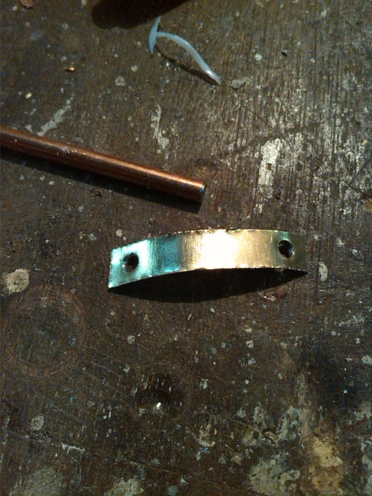
The next thing would be to attach the shafts to the ping-pong balls. This was achieved by cutting the tin into 20x5mm strips, drilling 1.5mm holes at the ends and soldering the shaft to the centre of the tin strip. Before soldering the tin and rod, ensure to ruff the surface.Once the pieces are soldered together you will then curve the surface of the tin and cant it back a bit to fit the profile of the sphere. Repeat this two more times.
Next I attached these to the ball halves, this was done with a nice idea, what I did was I placed the strips against the ball and marked holes. Next I piloted the holes with a large pin into the plastic, then used a heated metal rod to open up the holes to 1.5mm. I then found myself some 1.5mm nylon line for fishing.This was inserted into the holes and the metal strips.Once it is in the holes, take a blow torch and heat up the end of a pair of pliers, then when it is hot(warm enough to melt plastic), squeeze the pliers over the nylon line, so that it makes a flat rivet effect.
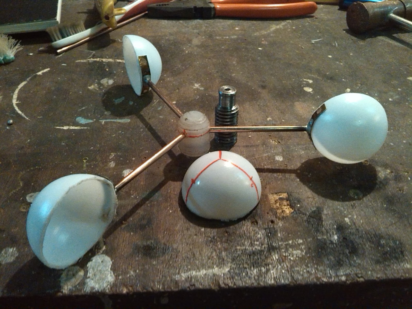
Next I turned up some things to hold the whole thing together. I went through quite a few ways in which to do this, working through ideas as I wanted to try other ways to do it than using a ball bearing setup. Although I ended up using the ball bearing in the end as it provided the best stability at high speed.
First one:
I made up a steel shaft and a nylon body that clipped together, the nylon would theoretically spin because of the 'loose' fit, yet stay on because of the lip. This idea worked, it clipped on, didn't come of without sufficient force, but it would probably spin if you put it in the way of a cyclone. The nylon has dimensions of $20mm * 15mm$, the nylon also has three holes just under the sphere shape, at $120°$.
 |
| Thread bar |
 |
| Adding the holes for the shafts |
 |
| Spare ball half used as top |
Second:
After I tried the design I tried to add a small brass pin that would sit in the indent on the top. This worked but still didn't give a nice response to the wind.
Third:
Next I thought of using a DC motor, that was very responsive and would have been nice to use, unfortunately the thing was a bit of a pain to attach to the final design. So I scrapped that idea as it was also going to be fun to extend the shaft of that I had.
Fourth:
I used steel rod again, and some solid brass rod. I then drilled out the brass rod as close to 3.2mm because of the drill bit being .01 too small. I then sanded the steel shaft with 1000 grit wet/dry cabinet paper, and then I also sanded the now brass tube with graduating grits of cabinet paper, starting at about 400 and going to 2000 odd. This was done with a dremel tool. You take a strip of sand paper, get a split pin, slip the paper in the pin and insert that into a dremel tool. Then you take this and put it into the tube when running and ream it out. This is done until the rod spun freely inside. Make sure you clean out the tube before insertion or it will grind out the inside with little burs when it is running. I ended up using this for most of the tests, as it seemed to work pretty well. But in the end I dropped it as it would get a sort of speed wobble.
 |
| $OD 4.7mm$ |
 |
| Brass soldered to strip of tin for tests. |
 |
| Used to hold the thing in place on the shaft | |
|
Before I changed over to the bearing style, I built the rest of the anemometer body. I first drew up the design and did an ISO. After it was draw I transferred the main points to the tin, so that I could use a compass to draw the development. I then used the compass with a sort of chisel thing I had lying around to score the metal. Then I cutout the development. This was then bent and rolled over a cylinder to get the curve and final shape of the base. I cutout and ground the top circle and the bottom one(which became of no use later). These were all soldered together and the brass shaft was inserted and soldered into the hole.
 |
| A bit skew |
 |
| Testing the original idea with the brass shaft through sheet. Allowing the motion to go inside the enclosure. |
The above setup was used to test the anemometer in some wind and it actually worked! Quite cool, but with the bearing setup the anemometer is able to pick up breezes better
I then sliced my thumb when cutting another piece of tin, when from the tension it was under it sprung back and the corner sliced the top of my thumb, I kinda saw some bone or other tissue. And it bleed a lot... surprisingly?
 |
| When you are not careful. |
Finally I moved to the bearing setup. This entailed redoing a nylon centre block, and a base for the bearing to connect to. I under cut the base so I needed to add some PTFE tape to get it to stay, not a real problem. The steel base was then attached to the tin plate. The old brass tube was reused on the wind vane later on.
Adding the small strip to the anemometer base, this is to allow it to attach to the $50mm$ PVC pipe.
 |
| problem with tape and heat. Nice show though |
 |
| Cleaning |
The anemometer and wind vane were then put on the roof for a few days, less the wind vane as it was not really stable at that point, this was just to test the design and its response. A
crude test setup.
The effects of putting the anemometer up with unpainted metal.
In conclusion it was an interesting build, learnt a lot, and went through a few designs. The whole design of the weather vane is drawn by hand and at some point I will scan and upload it. The wind vane construction will be in a second post.
For code and some designs(to come at this point) I have setup a
Github repo, it has some of the code that I used to test the anemometer and the theory code for the wind vane.
 |
| What it currently looks like |


No comments:
Post a Comment