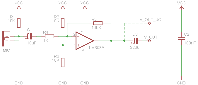
I was in need of a sound sensor board because I wanted to test some code that someone was experiencing issues with, so I scrounged around for some scrap parts and decided to make a free form circuit of the common sound sensor circuit, I used this as a base:
I made some modifications for the look of it, such as the ceramic caps and not the electrolytic ones.The modification I made to the circuit was the addition of a comparator using the free half of the LM358. That is what the green trim pot is for at the top of the circuit.
I used enamel coated wire from a stripped transformer. The other parts were from various PCBs I have collected... Hackaday calls it Fracking.
That seems to be about all the photos I took. But the idea is simple in that you take the wire and bend it around a cylindrical shape of your choice and arrange the curves to the way in which it best fits.
I ran two lines straight down the centre to get Positive and Ground along the sides where the OP-AMP power pins are. Also I ran the output from the final stage down the side too. Any other connections were made however they best fitted into the arrangement.


No comments:
Post a Comment