Sunday, 7 March 2021

Interesting point, is anyone actually visiting this site in 2021?

I am quite interested in seeing if this site is actually being visited by real people or it's just the bots having fun and confusing the google analytics and blogger algorithms, funny actually, but back to the point.

I would like to know, as supposedly the articles about ATTiny EEPROM usage get's quite a few visits each month and if it has been useful to some, it would be cool to know.

So if you happen to be reading this, and have found it useful, please leave a comment. 

Have a great day

👍

Sunday, 2 June 2019

A simple Laravel Flash message helper

I needed a simple way to ensure a one off flash message would show to a user on some of my larval apps, so I used the following idea


I recall seeing this implemented in a few places, so nothing new, it is just using some self explanatory styling and the bulma.io library for css.

I did make a tailwindcss version which I will update and add later :)

0_o

ATTiny EEPROM usage


Tutorial: Using EEPROM on the ATTiny Series of microcontrollers

 
ATTiny EEPROM Tutroial

Intro

This is the first tutorial by Barium Electronics that will be dealing with using the internal EEPROM of an ATTiny using the Arduino IDE and also using the AVR EEPROM library.

The Arduino EEPROM library is compatible with the ATTiny range of AVR microcontrollers as the library itself is built on the standard Atmel AVR avr/eeprom.h 'library' so it is compatible with all the AVR microcontrollers.

This was originally written back in 2016 (wow...) so some things may not match what people have floating around now :)

Things needed:

  • ATTiny of your choice, I prefer the t85
  • ISP programmer/ArduinoISP (Pocket ISP, USBasp)
  • Breadboard
  • Cup of coffee

Thursday, 13 October 2016

Arduino EMI shield

So a while ago I answered a question on Arduino.SE with regards to a person wanting to shield there Arduino from EMI( Electromagnetic Interference) that was coming from some AC they were feeding into a shield on the Arduino, and thus they asked if it would be plausible to use a shield in between the Arduino and the other device to stop interference. Thus I brought out some points to help that person.

Some things I answered in it:

  • Using DC Ground
  • Using AC Earth/Ground
  • Isolating circuitry 
  • Extra, PCB layout

Tuesday, 28 June 2016

Sound sensor with Arduino, freeform


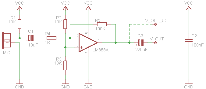
I was in need of a sound sensor board because I wanted to test some code that someone was experiencing issues with, so I scrounged around for some scrap parts and decided to make a free form circuit of the common sound sensor circuit, I used this as a base:
I made some modifications for the look of it, such as the ceramic caps and not the electrolytic ones.

The modification I made to the circuit was the addition of a comparator using the free half of the LM358. That is what the green trim pot is for at the top of the circuit.

I used enamel coated wire from a stripped transformer. The other parts were from various PCBs I have collected... Hackaday calls it Fracking.

 That seems to be about all the photos I took. But the idea is simple in that you take the wire and bend it around a cylindrical shape of your choice and arrange the curves to the way in which it best fits. 

I ran two lines straight down the centre to get Positive and Ground along the sides where the OP-AMP power pins are. Also I ran the output from the final stage down the side too. Any other connections were made however they best fitted into the arrangement.

Wednesday, 30 September 2015

General post on weather station

I have been busy with work and working on and off with the weather station. I have been working a bit on the FARS lately and have gone with plant pot basses with a 120mm diameter and made a 50mm hole in the centre for sensors and a 50mm PC fan I found/had lying around. I used 160mm 5mm thread bar by three, I used straws to hold each base at 10mm apart; each base is 20mm, 10mm is half way where the centre rim is, so it gives a nice overlap.

Friday, 31 July 2015

Weather Station - Anemometer

Copyright


So I have been working on the anemometer on and off for the last month as I have also been working on another project. I have also been working on the final design of the weather vane setup and slicing my thumb :) This will be part one of this part of the weather station, discussing mainly the anemometer.

The basic build

Tuesday, 7 July 2015

Weather Station - General Update

A general update of the weather station. The anemometer is coming along nicely, except for changes in final design and construction which I keep making. I am working on a build post for that, which should be up soon.

I received components I ordered the other day so that I can start getting some basic data.

I have a BMP180, DHT22, and 2 RFM12Bs, pictured below for fun:

I have so far tested the DHT22 with the library from Adafruit, it worked well.
I have yet to have some time to test the other stuff and also to find a suitable library for the RFM12 module which doesn't have a heap load of stuff added in. I also have to make level shifters for the two transceivers.

I got these through a local distributor for SparkFun Electronics who had reasonable prices, which is better than paying the import costs and overseas postage.

Wednesday, 24 June 2015

A new name! Barium Electronics

So I have been toying with some names for my business & blog as the name is representative of my blog and of my actual business I have. I have thus officially re-named my blog and business today as:

  •     The company is not too big that it will cause a huge mess with customers and my blog.
  •     Search the word Ziggy, Ziggy Electronics or ZE this gave some weird  results which are not fit for a business when customers search.
  •      Most people scoff at the name? Or at least a quizzical look, possibly the odd word.

So I have changed the name to something unique and more related to the electronics side:

Barium Electronics 


This is a name which is not used as a company name by anyone I can find. This should make the blog easily found by search engines as not much turns up in electronics projects, this should increase the traffic.

Sunday, 19 April 2015

Weather Station - Rain Gauge

tipping bucket arduino
For the first build post I will be starting with the rain gauge. This is based off the tipping bucket rain gauge method. These are pretty easy to make and get running.

Monday, 30 March 2015

Weather Station - Introduction

I have decided to dive into the adventure of building a functional automatic weather station(AWS), there are a lot of these projects on the web and are easily copied and pasted, but I feel this is not worth doing because you don't really learn anything from this.

What I plan to do is write a series of blog posts detailing the build process of the weather station, describing my build of all parts separately and then finally bringing it together in a final post and a permanent web app with forecasting and logging of weather for where I live.

I will be designing the station to be completely self-powered, this will be done by using a wind turbine and a solar panel, these will charge I am thinking of 3V coin cells, each one possibly powering a set of sensors and the micro.

The weather station will send the collected data to the base station located in the house and will manage storage and the method of either hosting or pushing the data to a storage site.

The station will contain the following functionality:

  • Temperature
  • Humidity
  • Wind Speed
  • Wind Direction
  • Barometric Pressure
  • Light Intensity
  • Visibility( or a sort of mist sensor)
  • Rain Gauge
  • Wireless Transceiver
I'll add more as I find other interesting stuff to monitor.

The base will have:
  • Display for sensed values
  • Wireless Transceiver
  • Storage
  • GSM to upload to server if needed
  • A display for the current or predicted weather
  • RTC
The Transceivers will be either 434MHz or the 2.4GHz range, although its only < 9m of distance between sensor and base(line of sight).

I also believe I might have a use for this site http://www.weewx.com/, it produces graphs and pages for weather station data and is LINUX compatible! Therefore the next logical thought is to run it on a Raspberry Pi which the system supports which will be awesome. 

Monday, 15 December 2014

Tiny Bot

This has probably been done to death on the blogs but I was inspired by the born 2 craft site. Mine needs a bit of work in the code but I generally prefer to do something from scratch by myself after seeing an idea. Mine is also a bit larger as it is veroboard.


attiny85 robot

Design


The parts are all hacked off of other dead RC toys and boards, ATTiny85 is the only thing I paid for, makes me happy. The system uses a small LiPo striped from crashed mini RC helicopter, nice and light. The board layout was worked out in building, working around the socket as it was meant to be a 8 pin PIC proto-board. 

The wheels were made from ABS sheet, using a circle template at 23mm. Using the four centre marks on the diameter I drew between opposite ones to get the point to make a hole for the shaft, I used a dividers point and checked every now and then to see the fit, just push on with reasonable pressure. 
I used marine silicon to create a tread. This is done by running two strips along ABS sheet at the distance of the wheels, and roll back and forth.

The battery is charged by a full spec LiPo balance charger through the headers, the switch is moved towards the header toput in charge mode.


Some build pics, some:


Underside

Front View

Hardware

The design of the circuit is similar to the born 2 craft, but I made some modifications.
I added the flyback diodes to the two motors, I skimped on those to begin with as there was not enough space, but after changing the transistors for both motors I added them. The PCB layout is my design.


  • Transistors are BC817-40
  • Diodes are 1N4148
  • ATtiny85/45
  • Small model motors
  • 0805 resistors
  • LiPo 3.7v
  • Switch SPST
  • Wheels: ABS, 23mm dia.
  • Some copper wire, varying thickness
Schematic
PCB

Code


/*
Tiny Bot: an LDR based light following robot, or avoidance bot
 if you switch the drive function around.
 Hardware is based off the Light Bot by born 2 craft

 TODO:
 Add IR control
 Clean up code
 ##############################
 Written by:
 Reece May 
 rev1 12/15/14
 https://ziggyelectronics.blogspot.com

You may use the code and modify it as long as you keep the above
and make edit notes bellow and put it on github here:
https://github.com/ReeceM/Tiny-Bot.git
 */

#define Rmtr 1
#define Lmtr 0
#define Rsens 3
#define Lsens 2
#define drive_time 100

int Rav, Lav = 0;

void setup(){

  pinMode(Rmtr, OUTPUT); 
  pinMode(Lmtr, OUTPUT);
  pinMode(Rsens, INPUT);
  pinMode(Lsens, INPUT);

}

void ADread(){
  Rav, Lav = 0;   //clear the average to prevent errors

  for(int q = 0; q < 20; q++){ //loop to create average

    Rav += analogRead(Rsens);
    Lav += analogRead(Lsens);
  }

  Rav /= 19;
  Lav /= 19;
}

void drive_RIGHT(){
  digitalWrite(Lmtr, 0);

  digitalWrite(Rmtr, 1);
  delay(drive_time);
  digitalWrite(Rmtr, 0);
  delay(drive_time);
}

void drive_LEFT(){
  digitalWrite(Rmtr, 0);

  digitalWrite(Lmtr, 1);
  delay(drive_time);
  digitalWrite(Lmtr, 0);
  delay(drive_time);
}

void loop(){

  ADread();
  if(Rav < Lav){
    drive_RIGHT();
    //drive_LEFT();  //use this to avoid light
  }
  ADread();
  if(Lav < Rav){
    drive_LEFT();
    //drive_RIGHT();  //use this to avoid light
  }
}

Links

https://github.com/ReeceM/Tiny-Bot.git

Saturday, 13 April 2013

3D PCBs

I have finally found a very good plugin for generating 3D PCBs. I found it on the Eagle Cad page, this took me to Eagle Up. Its got good directions on installing the plugins, even for me, ha. There is really good support from Jerome, the dude who wrote it, this was really helpful for me. 
Add something to this and you get a complete PCB rendering package. This is done by downloading MaxWell Render for SketchUp, as suggested by Jerome, this gives great results. the two pictures are of my redesign of the Little Wire for single sided home brew PCBs.


Friday, 10 August 2012

My new Plane!!

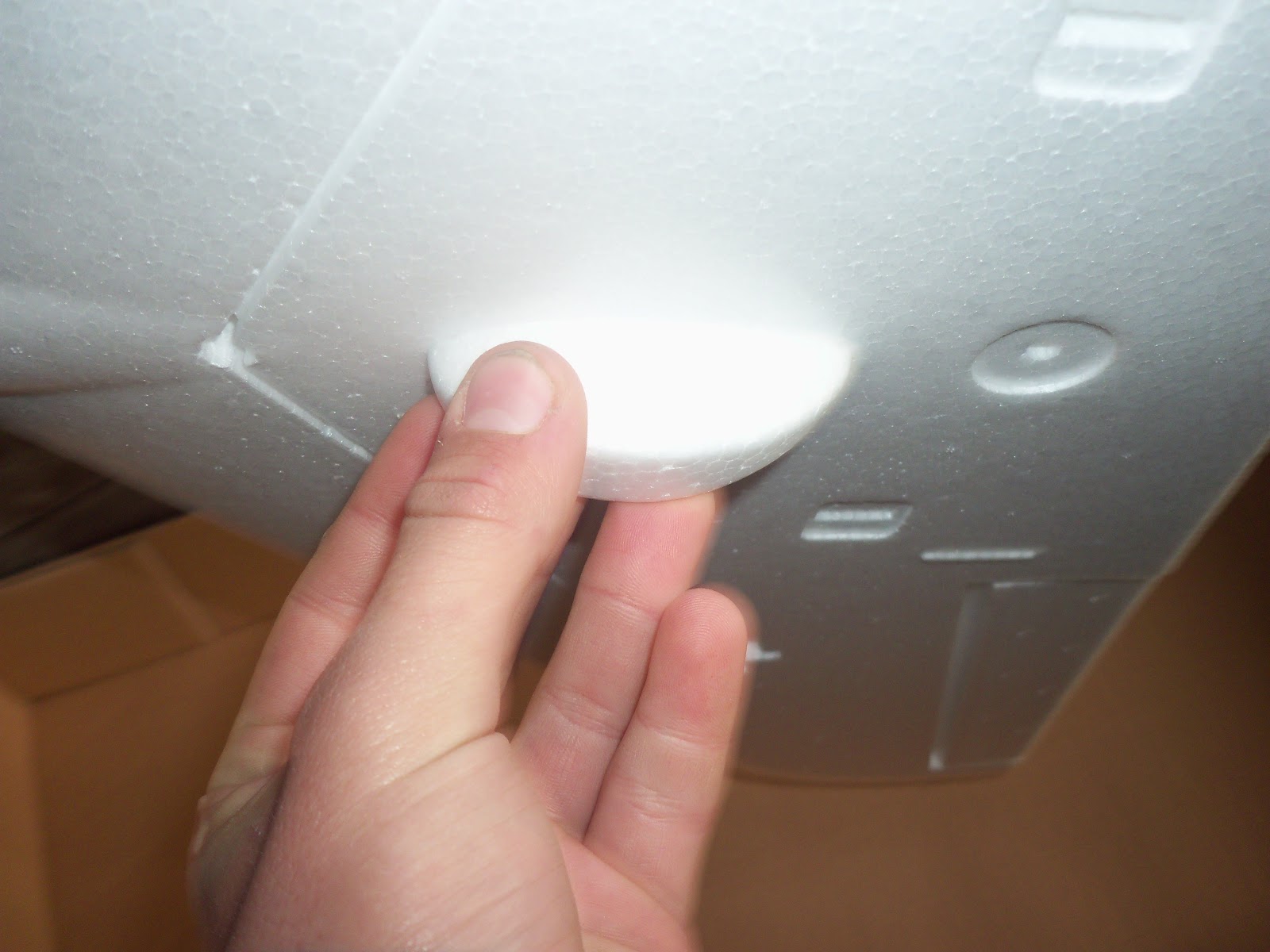
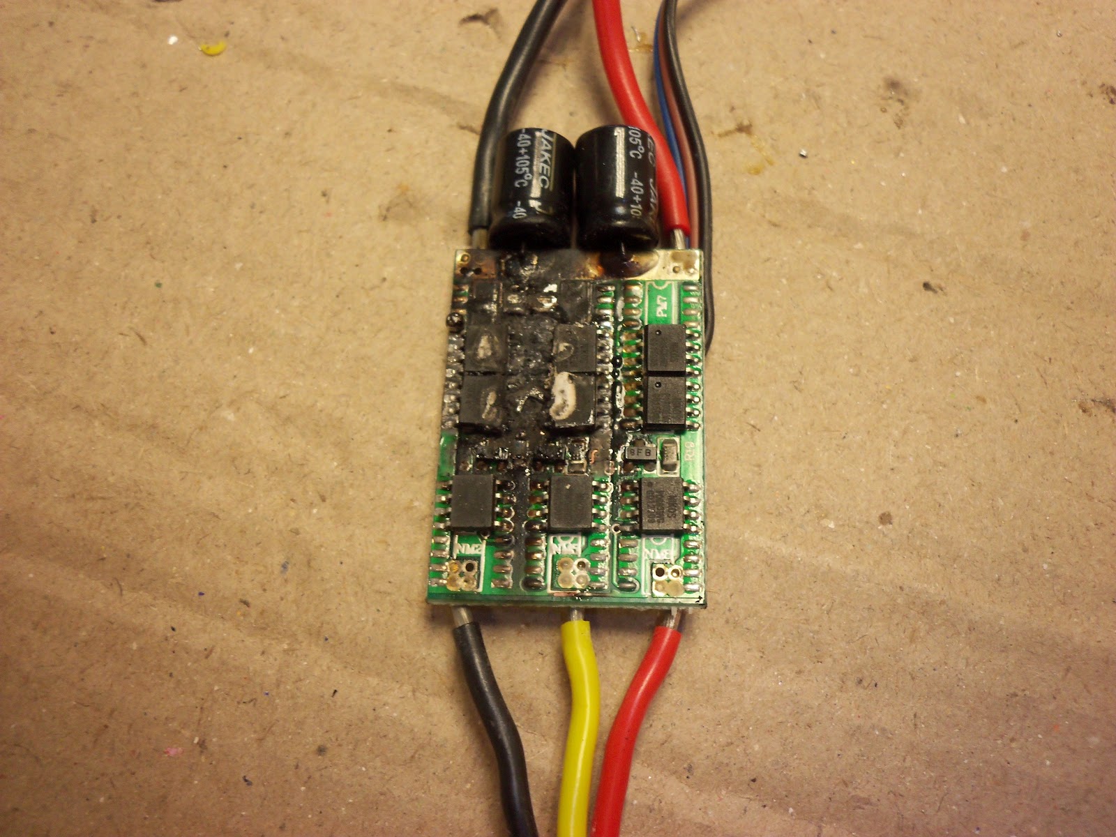
My new plane is a Fly Cat X-75 delta wing EPO plane. The kit was an ARTF style with ESC and brushless, but I had a lot of fun with the power-train. First the ESC was not working, get replacement, ESC makes smoke signals on bench testing (not even running), I then got a higher spec'ed one from my supplier and finally on the maiden the motor rattles around not cool. 

There is a brief video at the end and in those few seconds of panic I found my plane has a good glide angle and very responsive even when there is no thrust.

The Box...

The contents

Neatly rapped up.

Fuz

Tail feathers

Wing

Launch-grip and landing skid.

Supplied goods 

Together but Not.


Glued up and tagged.


After bench runs, highly under rated ESC

Cooked voltage reg. and 

the control IC's


New !40A! ESC and it works


What it looked like before flight and after.


The funny noise was the loose motor I sorted that out by adding shallow dimples on the lower part of the stator.